IndoorGML is an OGC standard for an open data model and XML schema for indoor spatial information. It aims to provide a common framework of representation and exchange of indoor spatial information. It is defined as an application schema of OGC Geographic Markup Language (GML) 3.2.1 .
Indoor space differs from outdoor space in many aspects. Basic concepts, data models, and standards of spatial information should be redefined to meet the requirements of indoor spatial applications. The requirements of indoor spatial information are differently specified according to the types of applications. In general, the applications of indoor spatial information are classified into two categories as follows;
Building construction and management and facility management belong to the first category. While the main focus of the first category are on building components such as roofs and walls, the second category is focused on usage and localization of features (stationary or mobile) in indoor space. The indoor spatial information of the second category is to represent spatial components such as rooms and corridors, and constraints such as doors. For example, indoor location-based services, indoor route analysis or indoor geo-tagging services belong to the second category.
The goal of this standard is therefore to define a framework of indoor spatial information to locate stationary or mobile features in indoor space and to provide spatial information services referring their positions in indoor space, instead of representing building architectural components. IndoorGML is intended to provide the following functions;
Note that the IndoorGML version 1 is based on the requirements from indoor navigation due to strong and urgent standardization demands, such as indoor LBS, routing services, and emergency control in indoor space. We expect that other requirements including indoor facility management will be handled by the next version of IndoorGML.
An important difference of indoor space from outdoor is that an indoor space is composed of complicated constraints such as corridors, doors, stairs, elevators, etc., like a road network space is composed of road constraints. It means that proper representations of indoor constraints are key issues of indoor spatial information modelling and standards.
Cellular space: indoor space as a set of cells, which are defined as the smallest organizational or structural unit of indoor space [Wordnet, Princeton University, 2010]. Cellular space has important properties. First, every cell has an identifier (namely c.ID) such room number. Second, each cell may have common boundary with others but does not overlap with other cells. Third, position in cellular space can be specified by cell identifier, although we may employ (x, y, z) coordinates to specify a position for more precise location.
Semantic representation: Semantic is an important characteristic of cells. In IndoorGML, semantics is used for two purposes: to provide classification and to identify a cell and determines the connectivity between cells. Semantics allows to define cells which can be of importance for navigation. For example, the most commonly used classification of cells in topographic space is into navigable (rooms, corridors, doors) and non-navigable (walls, obstacles) cells.
Geometric representation: The geometric representation of 2D or 3D feature in indoor space does not belong to the major focus of IndoorGML, since they are clearly defined by ISO 19107, CityGML, and IFC. However, for the sake of self-completeness, the geometry of 2D or 3D object may be optionally defined within IndoorGML according the data model defined by ISO 19107. There are three options to represent the geometry of a cell in IndoorGML as Figure 1;.
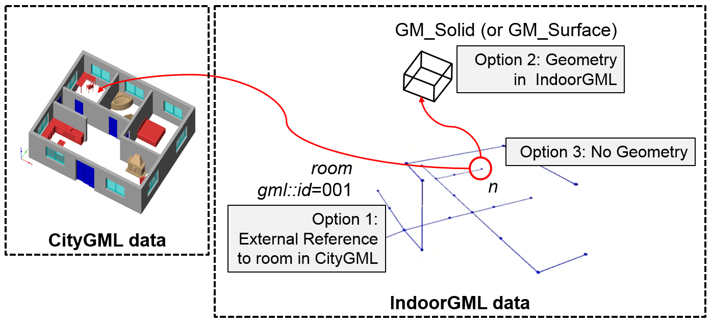
External Reference (Option 1): Instead of explicit representation of geometry in IndoorGML, an IndoorGML document only contains external links (namely c.xlink, where c is a cell in IndoorGML) to objects defined in other data sets such as CityGML, where the referenced objects in external data set include geometric information. Then there must be 1:1 or n:1 mappings from cells in IndoorGML to corresponding objects in other dataset.
Geometry in IndoorGML (Option 2): Geometric representation of cell (namely c.geom, where c is a cell in IndoorGML) may be included within an IndoorGML document. It is GM_Solid in 3D space and GM_Surface in 2D space as defined in ISO 19107. Note that solid with holes or surface with holes are allowed in this standard.
No Geometry (Option 3): No geometric information is included in IndoorGML document.
Topological representation: Topology is an essential component of cellular space and IndoorGML.The Node-Relation Graph (NRG) [J.Lee 2004] represents topological relationships, e.g., adjacency and connectivity, among indoor objects. The NRG allows abstracting, simplifying, and representing topological relationships among 3D spaces in indoor environments, such as rooms within a building. It can be implemented as a graph representing the adjacency, connectivity relationships without geometrical properties. It enables the efficient implementation of complex computational problems within indoor navigation and routing systems. The Poincaré duality [JR Munkres 1984] provides a theoretical background for mapping indoor space to NRG representing topological relationships. A given indoor space can be transformed into a NRG in topology space using the Poincaré duality. It simplifies the complex spatial relationships between 3D by a combinatorial (or logical) topological network model [25]. According to Poincaré duality, a k-dimensional object in N-dimensional primal space is mapped to (N-k) dimensional object in dual space. Thus, solid 3D objects in 3D primal space, e.g., rooms within a building, are mapped to nodes (0D object) in dual space. 2D surfaces shared by two solid objects is transformed into an edge (1D) linking two nodes in dual space.
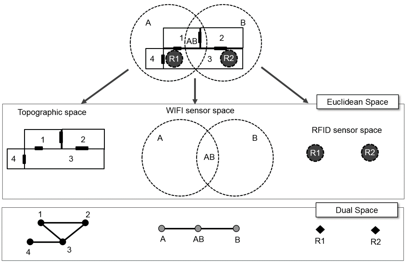
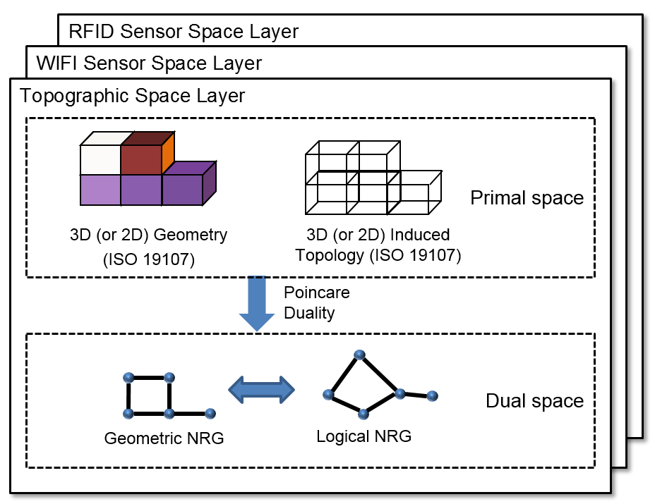
Multi-Layered Representation: A single indoor space is often semantically interpreted into different cellular spaces. For example, an indoor space is represented as a topographic cellular space composed of rooms, corridors, and stairs, while it is also represented as different cellular spaces with Wi-Fi coverage cells and RFID sensor coverage cells respectively as the following figure. For this reason, IndoorGML supports multiple representation layers with different cellular spaces for an indoor space. Each semantic interpretation layer results in a different decomposition of the same indoor space, where each decomposition forms a separate layer of cellular space.
IndoorGML is based on two conceptual frameworks namely Structured Space Model and Multi-Layered Space Model (MLSM). The Structured Space Model defines the general layout of each space layer independent of the specific space model which it represents. Each layer is systematically subdivided into four segments (see Figure 3).
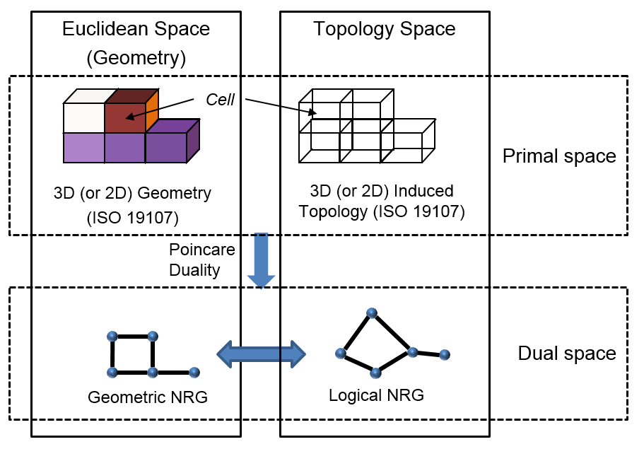
This figure illustrates the structured space model that allows for the distinct separation of primal space from dual space on the one hand, and geometry and pure topology on the other hand. This structure forms the basis for the framework proposed indoor space model. The upper and the lower part of the figure follows the rules of ISO 19107 for modelling geometrical features of real world phenomena, but the transition from primal to dual space cannot be modelled or described via the ISO standard. And topological relationships in IndoorGML such as adjacency and connectivity are not defined by means of the topology in ISO 19107 but by explicit associations within the IndoorGML data model. In the Structured Space Model, topological relationships between 3D (or 2D) spatial objects are represented within topology space (i.e., the lower part of the figure). By applying a duality transformation, the 3D cells in primal space are mapped to nodes (0D) in dual space. The topological adjacency relationships between 3D cells are transformed to edges (1D) linking pairs of nodes in dual space. Furthermore, the node of NRG is called state and the edge of NRG is called transition. The active state is represented by a node within the NRG and denotes the spatial area where the guided object is currently located. Once the object moves into a topologically connected area, another node within the NRG and thus a new active state is reached. The edge connecting both nodes represents the event of this state transition. The NRG representing topological relationships among 3D spatial objects in topological space is a logical NRG, while the NRG embedded to Euclidean IR3 space is a geometric NRG.
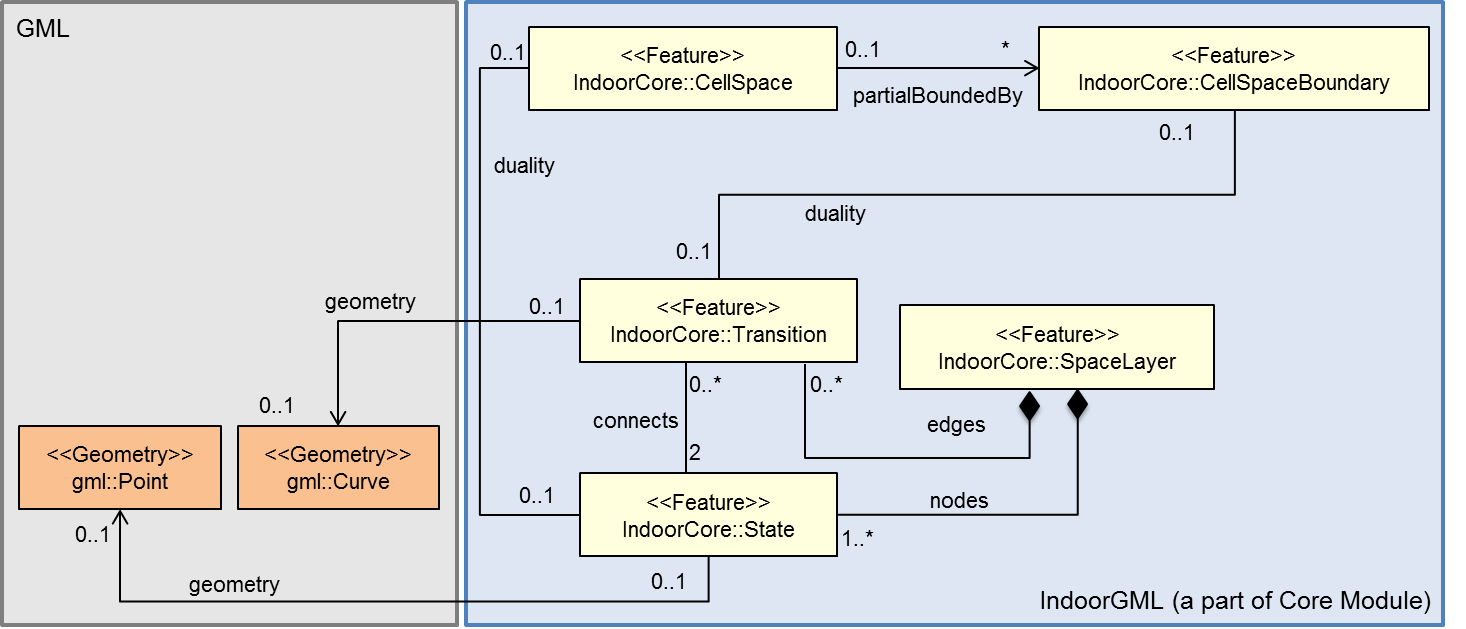
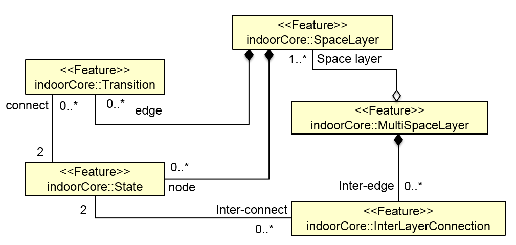
The UML diagram depicted in Figure 4 shows the data model for the Structured Space Model. A SpaceLayer represents a separate interpretation and a decomposition layer, and it is composed of States and Transitions which represent nodes and edges of NRG for dual space, respectively. The NRG and state-transition diagram for each layer are realized by SpaceLayer. Note that the current version of IndoorGML supports logical NRG and geometric NRG for dual space. As mentioned above, NRG as part of the Structured Space Model is implemented in IndoorGML model. In dual space, the logical NRG in the lower right part of structured space model as seen in the previous figure represents topological relationships among spaces in topological space, which is described as the cardinality of State and Transition to Geometry classes is 0 in this figure. When the cardinality is 1 in the figure, the topological model is implemented by coordinate space embedding of NRG (Geometric NRG), which is in the lower left part of structured space model as seen in Figure 3.
The concept of Structure Space model is further extended to Multi-Layered Space Model (MLSM). Multi-Layered Space Model provides an approach for combining multiple space structures for different interpretations and decomposition layers to support full indoor information services.
A same indoor space is often differently interpreted depending on application requirements as discussed above. It results in different decompositions of a same indoor space, and each decomposition results in a NRG. For example, the layers for topographic space layer, WI-FI sensor space layer, and RFID sensor space form independent structured spaces and each layer results in three separate NRGs as depicted in Figure 5.
Layers of multi-layered space model can be connected by inter-layer relations. In the following example of Figure 6, there are three space layers, where each layer constitutes a NRG. In a topographic layer, the nodes represent the possible states of a navigating object and correspond to cells with volumetric extent in primal space (e.g. rooms) while the edges represent state transitions, i.e., the movement of an object from one space to another. They correspond to connectivity relations between the cells in primal space (e.g., neighboured rooms connected with a door). In the sensor space, NRG has a slightly different structure. The nodes represent again the cells with volumetric extend (e.g. the entire coverage space of a WI-FI transmitter), while the edges represent the transition from one space to another based on the neighbouring WI-FI coverage spaces. Since the layers cover the same real world space, the separated dual graphs can be combined into a multi-layered graph.
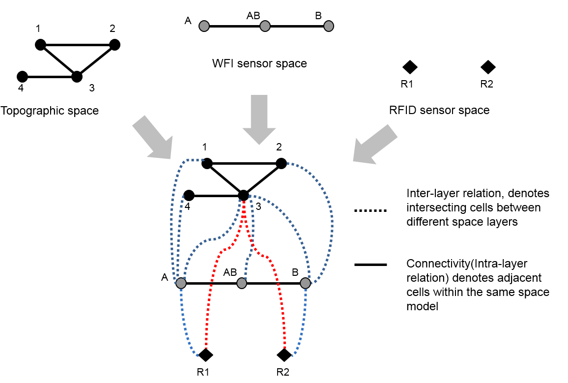
If we assume that each space model, whether it is for topographic or sensor space, is based upon a non-overlapping partitioning of space, a navigating object can only belong to one cell at a time and thus always only one state may be active. Therefore, an object is at any given time exactly in one cell (named state) in each layer simultaneously. This overall state is thereby denoted by the combination of active states from all space layers.
However, only specific combinations of states from different layers are valid and can be active at the same time. The combinations are expressed by additional edges linking the nodes between different layers. These so-called joint edges are derived by pairwise intersecting the cell geometries from different layers. A joint edge between two such nodes is inserted if the intersection of the interior of the two corresponding cells is non-empty. Therefore, the joint edges represent all relationships according to the eight relation model defined in [OGC Simple Feature Geometry] except “disjoint” and “touch” between two cells from different space layers and thus denote inter-layer relationships.
In IndoorGML, the space model for multi-layered space representation, called multi-layered space model, is implemented by MultiSpaceLayer class as shown in Figure 7. MultiLayeredGraph consists of SpaceLayers and InterLayerConnections, while SpaceLayer represents each space layer (e.g. topographic space layer, sensor space layer, etc.) and it forms a NRG composed of objects from State and Transition. The inter-layer relationships are implemented by InterLayerConnection class. In Figure 6, {(1,A,Within), (4,A,Within), (3,A,Cross), (3,AB,Cross), (3,B,Cross), (2,B, Within), (A,R1,Contains), (B,R2,Contains), (3,R1,Contains),(3,R2,Contains)} are the set of instances from InterLayerConnection class, where each instance represents the relationship between two cells of different space layers of Figure 2. The MultiSpaceLayer is an aggregation of SpaceLayer and InterLayerConnection.
Since the main focus of IndoorGML is on the notion of cellular space and topological representation, it may not contain geometries and detail semantic information of indoor features. Instead, IndoorGML provides a method to reference to an object in external dataset such as CityGML or IFC. Depending on application areas, indoor features may have different geometric and semantic representation models. For example, indoor spaces are often represented by grid model in robotic domain. By separating domain specific representation model from IndoorGML and providing external reference, a high level of flexibility can be achieved.
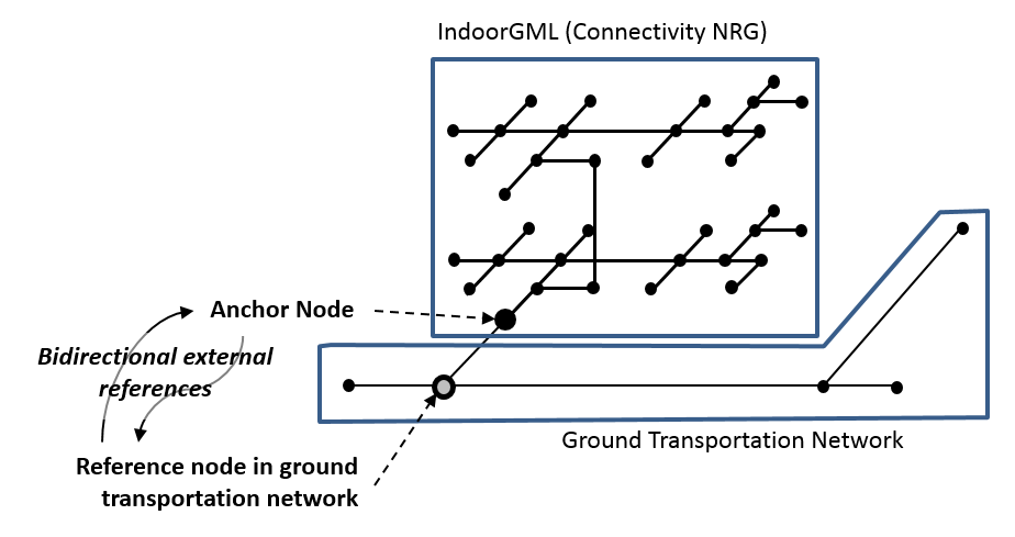
Connecting indoor and outdoor spaces is an important requirement of indoor spatial information. IndoorGML provides the concept of anchor node to connect indoor and outdoor spaces. We employ additional topology to connect indoor and outdoor space. Every indoor space contains at least one entrance, and it can be used to connect indoor and outdoor spaces. In IndoorGML, entrance is represented as a special node of topological graph in indoor space, connecting indoor and outdoor as shown in Figure 8. We call it anchor node, which differs from other node in topological graph, since it may include additional information for converting indoor CRS to outdoor absolute CRS.
Anchor node contains attributes to support the seamless conversion between indoor and outdoor spaces.
External reference to outdoor transportation network: Anchor node includes an external reference to a node in ground transportation network, which is connected to the anchor node as shown in Figure 16. Note that the relationship between anchor node and nodes in outdoor ground transportation is bidirectional. The anchor nodes are not only defined within IndoorGML document but also accessible from external data set such as outdoor ground transportation network. For example, when a vehicle is entering to a building, we can get the IndoorGML document of the building via the external reference from the node in the ground transportation network.
Transformation parameters: In many cases, a relative CRS is applied to an indoor space, and it is necessary to transform the coordinates of each point of indoor geometry according to the outdoor absolute CRS. Anchor node therefore contains the parameters for transformation;
In addition to the above attributes, we may include extra information such as radio map of the building for Wi-Fi indoor positioning.
Indoor space has often hierarchical structures and a careful decomposition of an indoor space is required in many cases to reflect hierarchical structures. A feature such as corridor or hall may be divided to accurately represent the geometric properties of indoor space based on the connectivity relationships among space objects.
The subspacing by the first option is explained in Figure 9. In the case of corridor of Figure 9-(a), node n6 in the NRG representing a corridor within the indoor space (Figure 9-(a), Figure 9-(b)) is considered as a consolidated Master Node, which is transformed to a sub-graph preserving connectivity relationship among the compartmentalized spaces of the corridor (Figure 9-(c)). It means that node n6 in the original NRG is converted into n6-1 and n6-2 and edge e1 in Figure 9-(c)) in the transformed NRG, which is a sub-graph representing a two-dimensional shape such as a hallway.
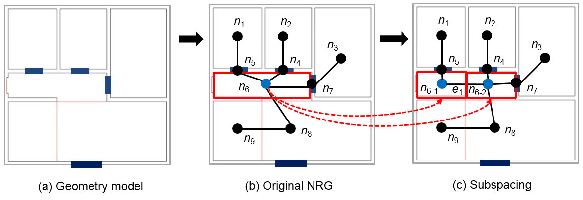
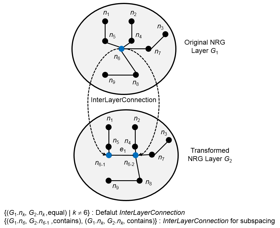
IndoorGML supports the subspacing by means of multi-layered space model to reflect hierarchical structure of indoor space as shown in Figure 10. The NRG G1 is the original graph layer with node n6, while G2 is a transformed graph layer with partitioned nodes n6-1 and n6-2. Then the hierarchical structure is represented by means of inter-layer connection of the multi-layered space model. Note that there are default one-to-one inter-layer connection between G1.nk, G2.nk except n6 as shown in Figure 10.
According to the OGC’s policy “The Specification Model - A Standard for Modular specifications” , the overall IndoorGML is split into a core module and extensions which have a mandatory dependency on the core. Therefore, the IndoorGML data model is thematically decomposed into a core module and thematic extension modules (see Figure 11). The core module comprise the basic concept and each extension module covers a specific thematic field such as navigation applications (e.g. pedestrians, wheel-chair, and robot). Each IndoorGML module is specified by an XML Schema definition file and is defined within an individual and globally unique XML target namespace. According to dependency relationships among modules, each module may, in addition, import namespaces associated to such related IndoorGML modules.
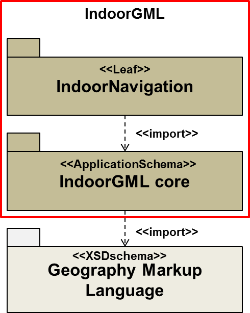
The IndoorGML core module defines the basic concepts and component of the IndoorGML data model. While the aspects explained in section 2 except semantic modelling are reflected into the core module, extension modules comprise the semantic modelling aspect of IndoorGML. Based on the IndoorGML core module, the extension module contains a logically separate thematic component of the IndoorGML data model. IndoorGML introduces the first thematic extension module, called IndoorNavigation module.
The dependency relationships among IndoorGML’s modules are illustrated in Figure 11 using a UML package diagram. Each module is represented by a package. The package name corresponds to the module name. A dash arrow in the figure indicates that the schema at the tail of the arrow depends upon the schema at the head of the arrow. For IndoorGML modules, a dependency occurs where one schema <<import>>s other schema and accordingly the corresponding XML namespace. In the following sections the modules are described in detail.